Saturday, July 16, 2011

Comparison Instructions


IN1 and IN2 are compared according to the type of comparison you choose:

==     IN1  is equal to  IN2


 >       IN1  is greater than  IN2


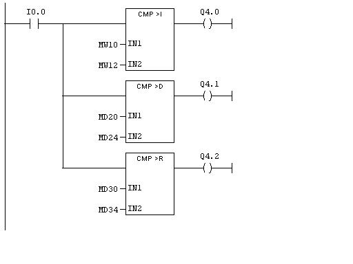
<       IN1  is less than  IN2


>=     IN1  is greater than  or equal to  IN2


<=     IN1  is less than  or  equal to  IN2


Bit Logic Instructions

Bit logic instructions work with two digits, 1 and 0. These two digits form the base of a number system called the binary system. The two digits 1 and 0 are called binary digits or bits. In the world of contacts and coils, a 1 indicates activated or energized, and a 0 indicates not activated or not energized.

---|   |---      Normally Open Contact (Address)
   ---|  |--- (Normally Open Contact) is closed when the bit value stored at the specified <address> is equal to "1". When the contact is closed, ladder rail power flows across the contact and the result of logic operation = "1".

When used in series, ---|  |---  is linked to the logic operation bit by AND logic. When used in parallel, it is linked to the logic operation by OR logic.

---| / |---      Normally Closed Contact (Address)
   --| / |--- (Normally Closed Contact) is closed when the bit value stored at the specified <address> is equal to "0". When the contact is closed, ladder rail power flows across the contact and the result of logic operation = "1".

When used in series, --| / |---  is linked to the logic operation bit by AND logic. When used in parallel, it is linked to the logic operation by OR logic.


Friday, May 27, 2011

Procedure for Configuring SIEMENS


Requirement
You must have opened a project or created a new project in the SIMATIC Manager.


 Basic Procedure
To configure and assign parameters to a structure, proceed as shown below: 


Creating a New Project

Requirement
You must have opened the SIMATIC Manager and opened a project or created a new project.  

Procedure
A station can only be created directly beneath a project.
  1. Select the project in the left half of the project window.
  2. Select the menu command Insert > Station > SIMATIC 300-
    The station is created with a preset name. You can replace the name of the station with a more relevant name of your own. 

Configure the Hardware

Requirement
You must have created a station (SIMATIC 300,).
Procedure
Select the "Station" object in the project window so that the "Hardware" object becomes visible in the right half of the station window.


Rack

Requirement
The station window must be open and you must have a plan of the hardware configuration of the station.


Procedure
Select a suitable central rack ("Rack") for your configuration from the ”Hardware Catalog” window; in SIMATIC 300 the Rail


Drag the rack to the station window.
The rack appears in the form of a small configuration table in the upper part of the station window. In the lower part of the window, the detailed view of the rack appears with additional information such as the order number, MPI address, and I/O addresses.
Alternatively to steps 1 and 2, you can also double-click the rack in the


Slot Rules (S7-300)
Rack 0:
  • Slot 1: Power supply only (for example, 6ES7 307-...) or empty
  • Slot 2: CPU only (for example, 6ES7 314-...)
  • Slot 3: Interface module (for example, 6ES7 360-.../361-...) or empty
  • Slots 4 through 11: Signal or function modules, communications processors, or free. 

Save and Compile


Download toPlc


Project Structure

Projects are used to store the data and programs which are created when you put together an automation solution. The data collected together in a project include:
  • Configuration data on the hardware structure and parameters for modules,
  • Configuration data for communication in networks, and
  • Programs for programmable modules.
The main task when you create a project is preparing these data for programming.
Data are stored in a project in object form. The objects in a project are arranged in a tree structure (project hierarchy). The display of the hierarchy in the project window is similar to that of the Windows Explorer. Only the object icons have a different appearance.
The top end of the project hierarchy is structured as follows:


Project Object

The project represents the entirety of all the data and programs in an automation solution, and is located at the top of an object hierarchy.

Station Object

A SIMATIC 300station represents a S7 hardware configuration with one or more programmable modules.

Programmable Module Object

A programmable module represents the parameter assignment data of a programmable module (CPUxxx, FMxxx, CPxxx). The system data of modules with no retentive memory (for example, CP312C) are loaded via the CPU of the station. For this reason, no "system data" object is assigned to such modules and they are not displayed in the project hierarchy.

S7 Program Object

A (S7)program folder contains software for S7 CPU modules or software for non-CPU modules (for example, programmable CP or FM modules).

Source File Folder Object

A source file folder contains source programs in text forma

Block Folder Object

A block folder of an offline view can contain: logic blocks (OB, FB, FC, SFB, SFC), data blocks (DB), user-defined data types (UDT) and variable tables. The system data object represents system data blocks.
The block folder of an online view contains the executable program parts that have been downloaded to the programmable controller.


Organization Blocks (OBs)
Organization Blocks (OBs) are the interface between the operating system of the CPU and the user program. OBs are used to execute specific program sections:


SIEMENS - Tutorial


SIEMENS ADDRESS

System Default Address Input     I124.0                      I124.7

                                         Output   Q124.0                    Q124.7


User Define Address Input           I0.0                           I0.7

                                                         I1.0                           I1.7

                                       Output     Q0.0                          Q0.7

                                                          Q1.0                        Q1.7


 Internal Memory Bit                    M0.0                           M0.7

                                                          M1.0                          M1.7

                                       Upto         M124.0                       M124.7


Integer       MW0 , MW2 , MW4 ,         Upto              MW124


Double Integer  MD0 , MD4 , MD8 ,     Upto             MD124

                                    Timer            T0   Upto  T255

                                     Counter       C0    Upto   C255

Tuesday, April 26, 2011

PLC Wiring

As the amount of current carried by a wire increases, it is important to use a wire with a larger cross section. A larger cross section results in a lower resistance, and less heating of the wire.


The standard wire gages are listed below: 


AWG #           Dia. (mil)         Res. 25C                  Rated Current
(ohm/1000 ft)           (A)

4                      204                  0.25
6                      162                  0.40
8                      128                  0.64
10                    102                  1.0
12                    81                    1.6
14                    64                    2.6
16                    51                    4.1
18                    40                    6.5
20                    32                    10
22                    25                    17
24                    20                    26


Monday, April 18, 2011

ALLEN BRADLEY PROGRAMING GUIDE


ALLEN BRADLEY

MODEL NO: MICROLOGIX 1200 SERIES C
INPUT: 14 & OUTPUT: 10
COMMUNICATION PROTOCOL: RS 232
TO OPEN THE SOFTWARE


Then select CPU model

FILE – NEW – SELECT  (MICROLOGIX 1200 SERIESC)


Hardware configuration:


DIGITAL INPUT/DIGITAL OUTPUT (14/10):

INPUT:        I: 0/0    to   I: 0/13

OUTPUT:   O: 0/0   to   O: 0/9

INTEGER:  N7:0     N7:255

FLOAT:       F8:0    F8:255

BINARY:    B3:0/0        B3:0/15
                        .
                        .
                        .
                        .
                     B3:255/0    B3:255/15

CONTROL
REGISTER: R6:0      R6:255

JUMP:          Q2:0   Q2:99
SUB ROUTINE: U:3     U:99

STRING:      ST9:0    ST9:255

ANALOG (2/2)
INPUT:         I:1.0 AND I:1.1
OUTPUT:     O:1.0 AND O:1.1

USER:
      NO CONTACT
      NC CONTACT
      LOAD
      LATCH COIL
      UN LATCH COIL


PLC SCAN PROCESS


The scan time indicates how fast the controller can react to changes in inputs.  Scan times vary with computer model and program content, and length.  If a controller has to react to an input signal that changes states twice during the scan time, it is possible that the PLC will never be able to detect this change.

PLC PROGRAM SCAN

During each operating cycle, the processor reads all inputs, takes these values, and energizes or de-energizes the outputs according to the user program.  This process is known as a scan.  Because the inputs can change at any time, the PLC must carry on this process continuously.
1.     I/O scan – records status data of input devices.  Energizes output devices that have their associated status bits set to ON (1)                 
2.     Program scan – instruction are executed sequentially.


Saturday, April 16, 2011

PLC OUTPUT TABLE FILE OPERATION

Processor continually activates or deactivates ouput status according to output image table file status

PLC INPUT TABLE FILE OPERATION:

Processor continually reads current input status and updates input image table file.


INPUT TABLE FILE OPERATION:


PLC PROCESSOR MEMORY ORGANIZATION

PLC PROCESSOR MEMORY ORGANIZATION

The memory of a PLC is organized by types.

The memory space can be divided into two broad categories:

Program and Data Memory:

Advanced ladder logic functins allow controllers to perform calculatins, make decisions and do other complex tasks. Timers and counters are examples of ladder logic functions. They are more comples than basic inputs contacts and output coils and relay heavily upon data stored in the memory of the PLC.

The user program will account for most of the memory of a PLC system.

Program files contain the logic controlling machine operation.

This logic consistes of instructions that are programmed in a ladder logic format.


DATA FILES:


The data file protion of memory stores input and output status, processor status, the status of various bits and numerical data.


PLC Architecture


What is a PLC?

PLC is a device, which is used to control a machine or process as per the human control sequence. A PLC monitors inputs, makes decisions based on its program, and controls outputs to automate a process or machine.

Advantages

Smaller physical size than hard-wire solutions

Easier and faster to make changes

PLCs have integrated diagnostics and override functions

Diagnostics are centrally available

Applications can be immediately documented

Applications can be duplicated faster and less expensively

PLC HARDWIRED CONTROL


Prior to PLCs, many of these control tasks were solved with contactor or relay controls. This is often referred to as hard-wired control. Circuit diagrams had to be designed, electrical components specified and installed, and wiring lists created. Electricians would then wire the components necessary to perform a specific task. If an error was made the wires had to be reconnected correctly. A change in function or system expansion required extensive component changes and rewiring.

DRAWBACKS:

Bulky and complex wiring.

Difficult to change the logic.

Unreliable.

RELAY :


RELAY LOGIC – AND GATE:

ELECTRONICS CONTROL


Logic gates and Electronic Circuits are used

Ease of programming

Ease of maintenance

Drawbacks:

Difficult to Troubleshoot while Change the Logic of the Process

Difficult to expand

Not suitable for industrial conditions


Friday, April 15, 2011

Plc Tutorial

AUTOMATION:
Automation is the use of control systems such as computers to control industrial machinery and processes, replacing human operators. In the scope of industrialization, it is a step beyond mechanization. Whereas mechanization provided human operators with machinery to assist them with the physical requirements of work, automation greatly reduces the need for human sensory and mental requirements as well.
ADVANTAGES OF AUTOMATION
The purpose of automation has shifted from increasing productivity and reducing costs, to broader issues, such as increasing quality and flexibility in the manufacturing process.
Automation is now often applied primarily to increase quality in the manufacturing process, where automation can increase quality substantially.
For example, automobile and truck pistons used to be installed into engines manually. This is rapidly being transitioned to automated machine installation, because the error rate for manual installment was around 1-1.5%, but has been reduced to 0.00001% with automation.
Hazardous operations, such as oil refining, the manufacturing of industrial chemicals, and all forms of metal working, were always early contenders for automation.